Testing CAM programs with SVG Part I (MakerCAM)
90 minutesA Simple Drawing
I would like to do some experiments with some simple SVG files and a few different CAM packages. To start with I’m created what I believe to be the simplest input document that I could think of which is a hand coded SVG square:
<svg xmlns="http://www.w3.org/2000/svg"
     xmlns:xlink="http://www.w3.org/1999/xlink">
    <rect x="0" y="0" width="100" height="100" style="fill:red;" />
</svg>
The cut will be along the outside of the square and it will be cut out of the material.
Physical Constraints
- The virtual material I plan to cut through will be 5mm thick plywood.
- I will also be using a 1/8 inch single flute, which may be complete garbage,
- Finally I’ll be assuming a spindle that runs at 12000 rpm.
Cam Software
MakerCam
- File => Open SVG File
- CAM => profile operation
- CAM => calculate all
- CAM => calculate all
- CAM => export gcode

Resulting GCODE
 1 (Generated by PartKam Version 0.05)
 2
 3 G21 G90 G40
 4
 5 (single cut)
 6 G0 Z15
 7 T0 M6
 8 G17
 9 M3
10 G0 X-1.5875634517766497 Y0
11 G1 Z-1.5 F1200
12 G1 X-1.5862944162436547 Y-35.276649746192895 F2473
13 G3 X0 Y-36.86548223350254 I1.5862944162436547 J0
14 G1 X35.276649746192895 Y-36.86548223350254
15 G3 X36.86548223350254 Y-35.276649746192895 I0 J1.5862944162436547
16 G1 X36.86548223350254 Y0
17 G3 X35.276649746192895 Y1.5862944162436547 I-1.5862944162436547 J0
18 G1 X0 Y1.5862944162436547
19 G3 X-1.5862944162436547 Y0 I0 J-1.5862944162436547
20 G1 Z-3 F1200
21 G1 X-1.5862944162436547 Y-35.276649746192895 F2473
22 G3 X0 Y-36.86548223350254 I1.5862944162436547 J0
23 G1 X35.276649746192895 Y-36.86548223350254
24 G3 X36.86548223350254 Y-35.276649746192895 I0 J1.5862944162436547
25 G1 X36.86548223350254 Y0
26 G3 X35.276649746192895 Y1.5862944162436547 I-1.5862944162436547 J0
27 G1 X0 Y1.5862944162436547
28 G3 X-1.5862944162436547 Y0 I0 J-1.5862944162436547
29 G1 Z-4.5 F1200
30 G1 X-1.5862944162436547 Y-35.276649746192895 F2473
31 G3 X0 Y-36.86548223350254 I1.5862944162436547 J0
32 G1 X35.276649746192895 Y-36.86548223350254
33 G3 X36.86548223350254 Y-35.276649746192895 I0 J1.5862944162436547
34 G1 X36.86548223350254 Y0
35 G3 X35.276649746192895 Y1.5862944162436547 I-1.5862944162436547 J0
36 G1 X0 Y1.5862944162436547
37 G3 X-1.5862944162436547 Y0 I0 J-1.5862944162436547
38 G1 Z-5 F1200
39 G1 X-1.5862944162436547 Y-35.276649746192895 F2473
40 G3 X0 Y-36.86548223350254 I1.5862944162436547 J0
41 G1 X35.276649746192895 Y-36.86548223350254
42 G3 X36.86548223350254 Y-35.276649746192895 I0 J1.5862944162436547
43 G1 X36.86548223350254 Y0
44 G3 X35.276649746192895 Y1.5862944162436547 I-1.5862944162436547 J0
45 G1 X0 Y1.5862944162436547
46 G3 X-1.5862944162436547 Y0 I0 J-1.5862944162436547
47 G0 Z15
48 M5
49 M30
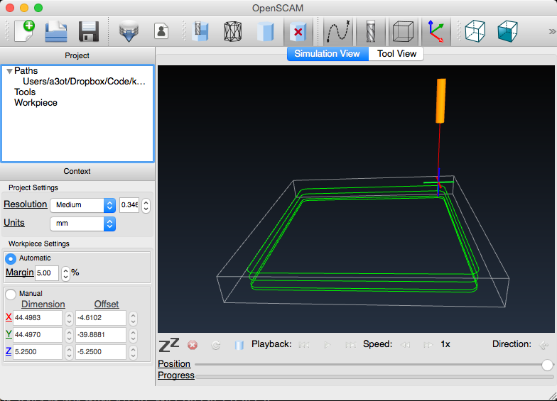
OpenSCAM Rendered Output

Future Posts
I’ll be evaluating other CAM software and their resulting GCODE. I’ll also be exploring how the differences in the generated GCODE will effect the machining of the part.
